Recently active
I am new to creo and I need to use Creo for this project. My version and Creo 4.0 M080. and I have a HP work station with i7-6820 2.70GHz, Quadro M3000M, 16GB ram. As I was trying to go thru the tutorial, even just trying to create a new sketch on a brand new part, rotating view, changing dimension, etc...it will freeze like 5~10 seconds everytime. I don't know what's the reason behind of all these freezes, my memory is only used 6gb, CPU is about 30% I found a similar topic https://community.ptc.com/t5/Assembly-Design/Creo-4-performance-issues/td-p/577222 but I don't know how to check all these
Hello, Does anyone know how to change the number of digits of a model's linear tolerances? My config settings for linear_tol are: 1 .1 1 2 .06 2 3 .030 3 so when I create a new model the tolerance comes in correct. I would just like to fix the issue on models that I create by saving from existing models that already have their own tolerance digit settings.
We are in need of a consultant who is very experienced in the use of the Piping module to review designs already done and provide guidance going forward with additional designs. These designs may also be done with Advanced Framework.Please send an email to me at the below address if you are or know someone who is capable of doing this work on a short term contract basis.We are suing Creo 4 m080 with WIndchill 11.0 m030 CPS16.Contact information: looslib@centrusenergy.com Posted here for better coverage.
Hi, Can anyone help me out and point me in the direction of some information about how to use the GUI components in Toolkit?I want to create a dynamic list box (contents of the list box is different depending on what the user does).I was hoping to figure out how to create a list box when I compiled the example "pt_userguide" that is one of the "examples" that PTC has provided in the installation.However the dialog which shows a list box is just loaded from a resource file (as can be seen in UgUITables.c) and that is all it does so this isn't helping.Is there a decent description somewhere of the API's that are used to create GUI components?Any help would be very much appreciated. Best regards, John Bijnens
Hi Everyone,Is there any way to make a coordinate system visualy larger, maybe my eyes are not what they used to be, but seeing what axis is what is difficult. Thanks.Bob Rizzari
Hi, I have an assembly drawing in which I'd like to eventually create a BOM. I'm successfullyl adding recursive items and would like to show the level in the assembly at which all the parts occur. When I add the rpt.level repeat region, it shows nothing. I have it successfully showing part parameters, index, quantity, but the level doesn't work. Do I need to do some configuring to get it to show? Is there a config.pro setting I'm missing? Thanks in advance.
Hi, our company have only just moved to Creo. I'm trying to create drawing sheets A4 to A1. I've started to make the A3 sheet and have a title block made up from a table. How do i create our company logo and add it into the cell within the title block? An idiots guide would be really useful....thanks.
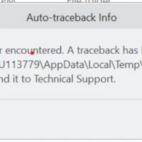
Hi! I have installed Creo Parametric Student Edition (for educational use only) on my computer. The program works correctly and there was no errors. But now I'm trying to add a new profile (I-beam) from AFX (in assembly: Framework tab -> New Profile). And again there's no problem with it - Creo gives me the profiles library, I can choose any profile from any category, next I can choose specific profile, and finally I can give dimension for the chosen profile. After these operations Creo shows me New Profile window (shown in the image below)......and when I try to click Next button, Creo shows the following error (shown in the image below).This error appears when choosing each profile. Could you tell me, please, if this is just Creo error and it could be fixed? Or maybe this is not an error and Student Edition doesn't serve operations as above?Thank you in advance for your answers!
Here's the next set of tutorials in the series of Creo tips from our expert product managers. Below you’ll find about 15 minutes of video how-tos to help you improve your CAD proficiency—whether you just started using Creo or you've been using it for years. Ready to get started? Make External References Independent of Their Source, by Default Feature dependencies can be either local or external references. Local references relate to geometry in the model in which they were created. External references (or external dependencies) occur when you reference geometry (parts, subassemblies) outside the model in which they were created. By default, external references depend on the model containing the geometry being referenced. The external feature depends on to the assembly where it was created, and every time you regenerate the parts or the assembly involved in the external reference, Creo Parametric looks for this feature’s references in the source par
Hello All, I am getting error "langLoadExtTbl: File "pro_i18n.res" could not be opened" when I am trying to load a session using a Jlink Async mode. I am trying it on Creo 3.0 Please help me out Thanks in Advance. Thanks, Swapnil
In this series, our expert product managers are going through how-to Creo tips. Each bite-sized tutorial is less than 5 minutes long. It's a perfect opportunity to learn something new or get a refresher on a workflow you haven't used for a while. Below you'll find about 15 minutes of video tips aimed at helping you improve your Creo proficiency. Ready to get started? Geometry Backups on the Fly When you create external references among features in a design, local references to features in a part, or placement references in an assembly, reference creation and backup tools are provided for specifying system behavior. In this tutorial, Arnaud van de Veerdonk, Creo Product Manager, shows you how to use Update Control functionality through, on-the-fly created, Geometry Backups. Watch the tutorial: Flexible Management of Item Visibility in MBD When working in model-based definition (MBD), three schemes are available to manage th
We are in need of a consultant who is very experienced in the use of the Piping module to review designs already done and provide guidance going forward with additional designs. These designs may also be done with Advanced Framework. Please send an email to me at the below address if you are or know someone who is capable of doing this work on a short term contract basis. We are suing Creo 4 m080 with WIndchill 11.0 m030 CPS16. Contact information: looslib@centrusenergy.com
Question I want to get my cable items on my BOM and to have BOM Balloons pointing to those locations The issue I am running into is when I try to add them into my BOM, I am no longer able to generate Balloons for the view that is attached to the repeat region. The existing Balloons stay in place on the connectors/terminals/contacts but I get an error stating "Invalid view for showing BOM Balloons for the region" The way I adding my cabling items to my BOM and keep the rep.index in line was adding an extra column that pulls the ERP part number for each spool from the creo spool file, maybe thats the issue? Maybe its the cabling? Help?
My company uses a common part on all of our assemblies. Recently, we received new, more detailed CAD of the part from the part supplier. The new CAD maintains all of the key dimensions of the old part, however it is much more detailed. Is there a way to update my part to the new more detailed geometry while maintaining all the original references in my assemblies? In this way I would not have to create a new part for the new CAD, and use the replace function in every assembly we have (because we have a lot). Thanks,
Hello everyone, I have a problem with the hole notes that IFX creates for dowel pin. Notes mentioned a threaded hole as in attachment while it should be a smooth drilled hole with tolerance. Could you please advise me on how to manage this issue ? Thanks
Hi all, Is there a way to save a Creo file without the model tree history? I need to send a large assembly in Creo format to a client, but I don't want him to have access to the parametrization. I know I can save as a step or igs and then convert to creo again, but I'm wondering if there is a more direct way to do this. Thanks
Hi all, using Creo 7 here. I'm trying to set up some drawing borders formats using tables. I don't want to merge the cells. No matter what i do i cant blank a table line. I've selected the whole table - line display - blank - select line....but doesnt blank it any ideas? thanks
Hello, I have the standard version of Creo3 M050 and i can't use the copy geometry and publish geometry options (it's gray) Do I have to activate them in the config.pro? If yes how? Do i need a additional licens for this? actual licens are: 4DNavigator, AE, Assyperformance, CDT, Data_for_PDGS, Detail, Design_Animation, Ecad, feature, flexible_modeling Thank you for your help 🙂
Hello, Our company is investigating model based definition for parts and assemblies. Going through the CREO 4.0 tutorial on PTC university, we haven't seen a start part for an assembly. Is there one available?
I go to save as, and try to save as DWG and it does nothing.
I have an assembly model that I need to place coordinate systems at the CofG position for both the computed and assigned results, is there a way of doing this via parameters? Each model in the assembly has an assigned CoG position and mass. At the assembly level I can get the assigned values using MP_CG_X etc but can't figure out how to get the computed values - any ideas please? Cheers!
Hi, i'm new on CREO (3 month). new job new company. i used to work on different software to create 3D harnesses. i have an issue today regarding Harness Mfg. we just got the licence i try to flatten simple harness. it work (sometime) but when i want to use a component to route my harness sometime it will work and sometime i got the following message: Unsupported Axial Topology when i remove the component from the path it will be ok, but i use the same component somewhere else and it is working fine so i don't understand what is happening. i think the part i use to route the wire is created properly as it is working fine somewhere else if someone has an idea i will appreciate. Thanks Ced1
Hi All I am using a VPN then Microsoft's remote desktop connection. Then using my computer at work with CREO 2.0 and Windchill etc... The graphics seem very laggy and big complex surfacing is difficult with the laggy / slow screen refresh rate. And I cant use twin monitors. Is something like "team viewer" better? Has anyone got any experience on this? David Hale / UK
Hello, I have a part with different colors, then export to parasolid, step and solidwks. When Solidworks open the parasolid file all colors turn to gray, but in the step and solidwks files all colors are show. Anyone knows why this happens?
good morning how can i simulate robot systems in creo parametric for paletize? i need simulated in creo parametric 3.0 a kuka robot kr120 with a gripper to move a cement bag between two conveyour belt, but a i not know simulate it. Can someone teach me? this is a similar proyect of an other person 2e jaars eindproject - De Gripper - Avans Hogeschool - Werktuigbouwkunde / Mechatronica - YouTube
Already have an account? Login
Enter your E-mail address. We'll send you an e-mail with instructions to reset your password.