Recently active
I work in WF3.I want to move a part in an assy along a certain line which I have sketched.It is a simple sketch (straight line/tangent curve/straight line).I create a ASM-datapoint on the sketch and use "ratio" to decide the point's relative position along the sketch.The moving of the part is controlled by adjusting the ratio between 0 and 1.Now comes my problem. The datapoint will not move along the full sketch - it will only move within the segment of the sketch where I defined it. I believe I must convert the sketch to a curve which I have tried, using <insert;datum;curve;copy>. Although the resulting curve appears to follow the whole of the sketch, the result is the same. When defining the data point, it will only move within parts of the sketch.I might add that if the sketch only consists of 1 item it works as intended.How do I convert my sketch to a chain which the data point regards as one curve?Using the option "through points" will only get me an approximation.&nbs
I developped a formula (thankS to the support of the Community here). The equations are quite long but I suppose for the MathCad engine it should be no problem.It just says the formula is too long to be displayed but it can be used for further calculation The problem is the following calculations stays grey too and they are not refreshed. -Formula calculation are not refreshed -Quite often I have to kill the task because Mathcad does not answer Any idea why this strange (and apparently random) behaviour ? Another strange thing is that when it works, the last formula does not simplify the units, although i defined mm:=10^-3m and gm=10^-3kg Any clue of what is done done properly? Note: I am using Mathcad Prime 9.0.0.0
Hello everyone We have just switched to Creo 11 from Creo 9 ( jumped 10 ) and I am finding that Creo isn't retrieving Chuck and part assemblies, and the retrieve missing component function is no longer on the right click mouse option. Does anyone have any ideas what is happening. I have checked my search.pro file and my paths are correct. I don't know if this started in Creo 10 as we jumped that release version. Thank you
I'm hoping someone might have a quick workaround. Some years ago we purchased 25 permanent academic student licenses of MathCad 15 from PTC. I understand that PTC no longer supports MathCad 15 and I've read the FAQs related to the changes. While the FAQs warn against the risks of continuing to use these licenses, it does say that permanent licenses will still work. Unfortunately when I now try to verify the Product Code through the MathCad License Setup Wizard and use the usual "acquire a license via the Internet" and then enter the Student educational Product Code along with my account login, an "Unexpected Error" window pops up pointing out that "The trial program software you are requesting is no longer available." It then points me to the website to purchase the latest version. The PTC licensing management team is aware of the issue and suggests that they are looking into recreating a permanent tool that will allow those of us with Product C
Hi Folks, I have what I think it s a simple question. Solve blocks seem to require a bunch of needless space. Is there any way to eliminate this? V15 solve blocks were a lot more flexible. Update: I asked a similar question about two years ago. I'm just trying to find out whether PTC has made any progress on this. Mark
This may be a silly question:- I recently started using CREO at work. I had a PC when I first got at work. They switched me out to a laptop.- I thought I remembered that CREO Versioned File Extensions (i.e. .1, .2, ... .50, .51) showed up in Windows FIle Explorer. Am I crazy?- I need to know the latest versioned file since this is how we manage rev control at our work - not Windchill here.- I remember the versioned file extensions showed up on my PC - now with my laptop I see nothing.- Is this a Window File Explorer setting - or a CREO setting?- So, when I have to upload a specific versioned file I have to use Windows sort by date to see latest.- Please help me see the actual versioned files in Windows Explorer or open/save dialog box.Thanks
I am in the IT dept of my company and we use Mathcad Prime 9. I have a user who wants to know if it is possible to convert MathCAD 2000 files to a Prime 9 compatible format. I am not seeing much online about this so my expectations are low, but if it is possible please let me know.
Hi,Seems that Mathcad Prime 10 does not allow anymore this. How to do in this case?
Is there a shortcut way of making optional parameters in a function in either M15 or Prime 3.0? I haven't come across anything regarding this issue yet.I ask as this would be a great way to implement the same function with some options. We could use [] to define the optional parameter with the number inside defining the default value.
Hi there,I have a rather long (50+ pages) mathcad (Prime 9) sheet that I have built to be fully parametric. After changing one of the variables I suddenly find that one of the functions is not working as intended without an apparent reason. I have located the source of my problems, but I cannot seem to comprehend why is it throwing this error. I am using root function to solve for the location of the critical x as shown below. In my previous iteration for a different set of input parameters, this function worked as intended, but as I changed one (in this case L, though I doubt it matters too much), I am getting an error that these values cannot be compared even though they are clearly the same unit and allow for algebraic operations such as addition, subtraction etc, but when compared against another variable of the same unit I get this error. If I manually create a new variable, lets say y.crit and give it the exact same value ( through key input ) everything works again, th
I found the config option for naming a sheet metal flat pattern representation and wondering if there is one that will automatically name a flat pattern instance to some other default name. We would like the flat pattern name to be <part number>-600 like we are doing for the rep. Creo 8.0.0.0 Thanks...
Hi,Why is it written that for subscript in text one needs to press ctrl+- and for superscript in text one needs to press ctrl++, while if someone press ctrl+- and ctrl++ it comes out of the way of being able to use subscript and superscript in the text. Is this indication written wrongly?
Given an ellipse E in the Cartesian coordinate system with the semi-axes a > b and the equationx^2/a^2 + y^2/b^2 = 1. A chord AB of fixed length s < 2*b is considered. Let the point P be fixed on the chord so that the chord is divided into the segments AP = u and PB = v, i.e. u + v = s. The points A and B should now be moved on the periphery of the ellipse in a rotational direction while maintaining the chord length s and its pitch P in u and v. During this movement, point P describes a closed curve K.The content of the annular area bounded by E and K is sought.
I am using Creo 8, and I am having problems publishing an AR experience of one of our larger assemblies, it fails, but I do not get any helpful feedback from the status bar or the popups is there a better way to see why it is failing? I have been able to publish this assembly in the past, during a round of checks from my team we found a couple issues that were fixed on the Creo side, but when trying to publish again it is failing. I have tried to publish other smaller assemblies and they are hit or miss, I have published single part files and it is also hit or miss. I checked and it is not a firewall issue from what I can tell, but going to the https://app.ar-design.ptc.io/ site is very slow and occasionally will error out. Thanks!
Why is the PTC process so convoluted?😫😫 This is the reason I never use PRIME and stick with MATHCAD 15. I am one of the respondents totally disgusted with PTC as noted on this forum thread.https://community.ptc.com/t5/Mathcad-Installation/MathCad-15-permanent-Product-Codes-no-longer-verified-by-PTC/td-p/815892 In order to help a friend decide on PRIME, I downloaded MATHCAD EXPRESS, actually PRIME 10 30 day trial. It supposedly installed because there is a PRIME 10 exe file. I downloaded the license from my email. When I try to run MATHCAD PRIME 10 for the 30 day trial nothing happens when I click on the MathcadPrime.exe file in the PRIME 10 folder in Program files. It never asks for a license; it never installed a desktop icon. It never showed up in my Start Menu. Their so called instruction guide is pages long with no succinct summary. I don't have time to study a lengthy installation guide for such a convoluted p
Hello sir,I've been using PTC Mathcad for buck converter design calculations. But we want to draw block diagram in mathcad. Is it possible, need support!!Regards,Krushna Thete,Accolade Electronics Pvt Ltd
I have MC Prime 9.0 and I've just install MC 10.0When I try to open existing worksheet (created previously with 9.0) it does not open with MC 10 but with MC 9.0.When I create and save new worksheet in MC 10 and try to open later on it, it tries to open it with MC 9.To open it in MC 10 I have to open blank worksheet first and then load desired file, kind of annoying.How to force opening old and new worksheets with MC 10? Do I have to remove/disable MC 9?
I was writing up the one of the Mathcad examples for CHAPTER 8: Earth Retaining Structures8.2 Reinforced Concrete Retaining Walls with Sloping Backhill. Could you please help me finding why the error massage was showing up?
Can you please help me solve this issue? I don't see any faults on equation. Please let me know if I am overlooking at something. Thank you.
I NEED HELP TO UNDERSTAND WHAT THESE CIRCLES ARE ON THE SKETCH LINES. EVERYTHING LOOKS GOOD, CLOSED LOOP AND COMPLETE CLOSED LOOP PROJECTION OF THE SKETCH LINES I AM TRYING TO PROJECT A SKETCH TO OFFSET A CURVED SURFACE, AND AN ODD SURFACE (SEE PICTURES). THESE ARE THE STEPS I'VE TAKEN:* SKETCH* PROJECT SKETCH (I ENSURED ALL PARTS OF THE PROJECTION WERE CONNECTED, AND ON ALL SURFACE(S) OF THE PROJECTION)* SKETCH-PROJECT SKETCH (SKETCH SHOWS IT IS A COMPLETE LOOP(S))* OFFSET- EXPAND (SELECTED ALL SURFACES)NOTHING, I CANNOT GET EITHER A POSITIVE OR NEGATIVE EXPANSION (OFFSET ABORTED; GEOMETRY COULD NOT BE CONSTRUCTED)I DO NOT SEE THESE CIRCLES IN THE ORIGINAL SKETCH THE GREEN OUTLINE IS ONE AREA TO PROJECT TO FOR AN OFFSET, AND THE ORANGE AREA IS ANOTHER YOUR HELP IS APPRECIATEDAIRMAN DILLARD
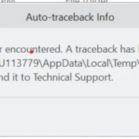
I am using Creo Parametric Release 8.0 and Datecode8.0.6.0During the rebuild of 2 separate parts I use edit references to walk through the model tree and re-define the references of each feature.For one part it works fine, but in the other part I encounter problems.Creo crashes using edit references. When using edit definition to re-define the features creo does not crash.How is this possible?What can be the root cause?Here are the errors that I facedFatal error encountered.
I have a 3D frame model and I want to add mass to a point to locate the CG of a component. The Help section says to use the Refine Model --> Mass function to do this, but I haven't been able to locate that function on the Ribbon, or in any of the Toolbars. Where is this located? https://support.ptc.com/help/creo/creo_pma/r10.0/usascii/index.html#page/simulate/simulate/add_mass_pt.html
Hello, Please let me know if PTC still officially supports Mathcad Prime 7. Is there any official PTC link where it is stated that this version of the Mathcad Prime software is officially supported? Warm RegardsVijay
Model and Sketch dimensions are not highlighting its only showing small square boxes
Hi,I am making something wrong? Are only 3 differential equations... But using laplace command this system of differential eq can be solved: See MCP9 file attached.
Already have an account? Login
Enter your E-mail address. We'll send you an e-mail with instructions to reset your password.