Temporary Image Upload Issue
Recently active
I am using Creo Parametric N/A N/A要移除子项 (30000444-seven-0734k02a00.prt),父项(10400820.drw)对象也应移除
I am using Creo Parametric 2.0 M100要移除子项 (30000444-seven-0734k02a00.prt),父项(10400820.drw)对象也应移除如何在drw文件中查找prt?
Hi, While working on Creo 5.0 Parametric Part modeling Experience Fatal Error warning pops up and the program closes, A Traceback file is generated, Screenshot attached. Please suggest a solution.
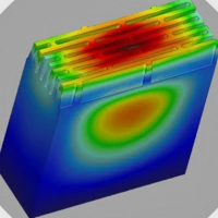
My group is working on a water bottle project and we need to simulate the thermal conduction of our water bottle design. Our teacher suggested that we "use water in the bottle", but we can't find anything to show us how to do that. Any suggestions are welcome.
Hi everyone, I need to convert a library created in Emx 5.0 with .dat files to be read by Emx 13 is it possible? I understand that now in the .dat files in addition to the variants, the information of the positioning axes and the surfaces for contouring are also included. Thanks
I am using Creo Parametric - Release 4.0 (connected) 4.0 M030I try to open certain .prt files from a customer and it gives message that it " cannot be retrieved.I try to open an assembly and some ot the .prt files are not visible. the .prt files in the folder that cannot be retrieved.I talk to the customer and they do not have this problem.Here are the errors that I faced " filename" cannot be retrieved.
Hello, I am new to Creo parametric. I am getting "Startup of Application failed" dialog popup when I try to run a jlink application through Auxiliary Applications option under Tools menu. This jlink application is calling some cloud Rest APIs. If I remove these Webservice calls, then the jlink app runs fine. Is there any option to call external REST services from Creo Parametric? Or any option to trigger separate program which in turn can call these web services? Thanks, Apoorva
I am using Creo Parametric - Release 3.0 (connected) 3.0 M080Suite à un reboot de serveur nous avons encore un souci de licence…L’une de nos deux licences est bloquée …Une fenêtre "License request failled for feature" s'affiche.Erreur 7788@server-proeng:(61) con not read license file data...Here are the errors that I faced Une fenêtre "License request failled for feature" s'affiche.Erreur 7788@server-proeng:(61) con not read license file data...
Hi,I'm using Creo Parametric 3.0 with basic AFX licension right now. In my project need numerical names for all profiles (e.g.: J900-000-01, J900-000-02, J900-000-03, etc... inside the assembly). I noticed that Creo automatically increments newly created profiles by giving them my-prefix_profile-type-name_auto-increment-number name (e.g.: J900-000_PROFILE_45X90_1). the only thing I need is to remove the _PROFILE_45X90_ suffix which Creo adds automatically. I tried to find it out but even inside Project Parameters I didn't found the option which could be helpfull. Do you know how can I achieve that? Thank you in advance for all replies!
Hello, I am using Creo 4 and trying to use IFX ( intelligent fastener exchange) tool to swap the hardware. On a hole size of 9mm dia, the tool picks the M8 bolt which is correct. And if i go to another hole of 5mm dia the tool still defaults to M8 bolt size which i think it is memorizing the previous execution selection and defaults to same hardware. Is this a bug ? or any config settings i can look into . Thank you in advance Arun
I am using Creo Parametric 3.0 M190file created a traceback.log when saving file. file opens ok, modify family table. Verify family table all instances are successful. When you select save the traceback window appears. select OK. Creo closes.
I've an assembly with a lot of parts assembled in a plate. Now I need to transfer the holes from the assembled parts, to the main plate. I need to mantain them parametrized according the dimension of the hole of each part, and the same time the amount of the holes of each part (pattern by reference). Doing this hole by hole, or even part by part, is really painfull... I've tested IFX, and I think isn't that versatible, because when we add or remove screws, we need to do a lot a things to update. My question is, what methods do you use to make this task?
Hello, I want to add maximum dimension to view for that I calculated the box size , try to find the maximum distance between two faces, for that I used ProselectionDistanceEval() function but it doesn't work , it give distance zero for all iterations , please help me to resolve the issue .
Hello, I want to add dimension to view , for that I get solid model from view , and get edges and vertices from solid , but now I want to check the edge is visible in view or not , want to transform the edge position in view , please help me to solve the problem
I am using Creo Parametric 3.0 M190 When I cancel a feature creation, another feature disappears. It did not occur in M160. (M178, 180 have not been verified) It also occurred in Creo 7.0.4.0
I have a part of which I would like to add a simple rep (with less features) in the drawing. I relate the BOM to this simple rep, but the material all of a sudden does not appear in the BOM anymore. It still shows up when I relate the BOM to the master rep. If I compare model properties of the master rep and the simple rep, one value changes but I cant figure out where to change this value. Does anyone know whats going on? see images:
Hi, Creo Parameter 7.0 My laptop is Lenovo Thinkpad P1 Gen 3 I use decal for 1st part and set appearance for 2nd part. Please help me how to fix it ? I use NVIDIA Quadro T1000 with Max-Q Design
Hi all, I am trying to use custom hole chart in Creo 7. Everything is OK except that the call out of standard holes are not attached to the cosmetic threads. Fig.1 According to our company standard, it should look as in Fig.2 (the arrow always points toward the center, and it is attached to the thread) Is there any way to achieve this? Fig.2 If you have any ideas, please let me know. Thank you so much!
So I am starting a new project where I will be modelling a front bike derailleur. I want to model the object accurately using exact measurements taken from my bike and the derailleur. How would I do this? The surfaces I created in the past didn't need to be exact, thus I used Style to create the curves and Boundary Blend to create the surfaces. Style does not use exact measurements(as far as I know). What method or tool could I used to create my model?
Hi, I am trying to call the toolkit function from VB api as per example given in article CS252032. DLL loaded but ExecuteFunction throws pfcExceptions::XToolkitNotFound error. Can anyone success in this method. Please guide.
I am using Creo Parametric - Release 5.0 (connected) 5.0 5.0.6.0DLL was unlocked on Creo 5.0.0 does not work on Creo 7.0. Get error message as "Creo tool kit application "" was not unlocked before distribution to your site.". Do we need to unlock the dll for every version separately??Here are the errors that I faced Creo tool kit application "" was not unlocked before distribution to your site.
Hi, Create the Table UI using the C++ Toolkit.The rows in the table display the components of the active assembly in a level structure.Each row displays the name and information of the component. Now we need to display the visual element of the component corresponding to the selected row.How can I display a visual element (Thumbnail or Image) of a selected component? If you have any good ideas, please share them.
In Creo cabling, if we want to update netlist information, the right process is to "Clear reference" -> "Import Logic data" and then "Update". This process works only in the component(or connector) level, but in the pin level, the residual information is remained and cannot be updated or refreshed completely. Since we use customized pin information to present the connection table in flat drawing(such as "&mbr.connprm.pin.signal.xxxx"), that means this residual issue will present out-of-date or wrong information in the table when updating a flat drawing. However, our solution is to proceed "Undesignate" -> "Designate" -> "Update" for a connector, so that all pin information in this connector can be refreshed and completely align with the latest logic data. But that means designer need to do this for every signal connector manually one by one whenever the schematic is revised, which is a big issue for our drawing process. Is
Hi there, I've been trying to use the flow analysis in Creo 6 to model a relatively simple lubrication system, however my tessellation is filled with holes and producing meshes that are in a word: chaotic. I'm fairly confidant this the source of the errors in my results as having been over it several times I've been unable to find anything else that looks amiss. Below are a couple of images to help clarify the problem. An example of the tessellation around the input: An example of a mesh over the whole system: If anyone has an advice as to how to correct this, it would be greatly appreciated.
The way that Creo allows you to assign a specific mechanism position setting to a drawing view is by creating a snapshot of the assembly and toggling the option to make that snapshot available in the drawing. The problem is: applying that snapshot to a drawing view is done by setting it as the "explode state" for that view. This means I can't make an actual exploded view where the mechanism position setting is frozen to what I want. If I choose to apply an actual exploded state of the assembly to that drawing view, then the mechanism position is no longer fixed; i.e. the view will change (messing up notes and balloons) based on whatever state of the mechanism is applied in the assembly model. Note that this also is a problem for section views. The section hatching is determined by the current state of the assembly model - not the drawing view - even after assigning a mechanism snapshot state to that drawing view. Has anyone developed a work-around
Already have an account? Login
Enter your E-mail address. We'll send you an e-mail with instructions to reset your password.