Recently active
I use a Logitech MX Master mouse with CP4. I started a new drawing yesterday where I'm creating draft dimensions. Middle mouse to place or complete Edit Attachment isn't working. It's behaving like a command cancel function. I am a bit rusty on drawings, but we've been on CP4 for 2+ years (and Creo/ProE a lot longer). Most of my work tends to be in part/assembly mode. And most of the time we use model instead of draft dimensions on the drawing. I've created draft dimensions before and I don't remember this being an issue. Work-around is to tap the middle button on the track-pad on my keyboard. But that is kind of tedious and non-intuitive to have to use that for the one operation that doesn't work with the mouse. Funny thing - the middle mouse works everywhere else. Inside part / assembly mode, you can click the middle button to confirm Done, spin/pan/zoom work with the Ctrl- and Alt- keys. Wheel to zoom works.&
Hey everybody, I want to export a 2D geometry into a stl file. So far I created a sketch with the 2D geometry, which I can‘t export to stl. I know that stl is actually for 3d volumes but in Siemens nx you can also export 2d geometry into stl files. Is there a way to do so in Creo? I used the fill command to generate a face of the sketch but I can‘t export the face to stl either. Someone Haus an idea? Best Tim
Goodmorning everyone,is it possible to release a series after it has been made in such a way as to modify every single feature that has been created with the same series?As you can see in the attachment I have made a series of numbers.I would need to release the series in order to change the number.Or is there a way to do this? ty, matteo
HI , When i open a model on CREO 6 , some componets is missing , so i must retrieve them manualy. I have all my componets on subfolders in 3d_library folder , and search.pro file refered on those subfolders . In the model tree , componets 08021800_kabiles_m8x30 , are located in the same main folder with the missing componets. The missing componets on the second abstract , model retrieve them , if i make regen twice. Attached abstract from , config. pro , search.pro file on ,D:\CREO_CAD_CAM3D ! KABILIES"D:\CREO_CAD_CAM3D\3D_LIBRARY\KABILIES""D:\CREO_CAD_CAM3D\3D_LIBRARY\PODIA_KOYZINAS""D:\CREO_CAD_CAM3D\3D_LIBRARY\SCREWS" and location of componets in subfolders on 3d_library folder D:\CREO_CAD_CAM3D\3D_LIBRARY\KABILIES. (ok, retrieve them , componets 08021800_kabiles_m8x30) D:\CREO_CAD_CAM3D\3D_LIBRARY\SCREWS (need retrieval , missing componets) D:\CREO_CAD_CAM3D\3D_LIBRARY\PODIA_KOYZINAS (second missing i
Hi all! Is there any way to get Windchill EPMDocument number using JLink? Thank you.
I commonly use 3D modeling to create surfaces and then export for fluid analysis in other software. The most common way to do this is to create a watertight surface and then export it in STL format. I can not figure out why, but it does not seem that Creo allows this. If I create a solid part, the STL option is available; if I create a surface though, it is not. Can someone tell me if there is any way to export a surface directly in STL format from Creo? If there is no direct method, is there a work around?
I am having an odd error where when I export a Creo View file, of the ~20 Combined states (showing my assemblies subsystems), only 1 of them is showing the annotations which I have assigned to the combined state I have checked everything but the states all appear good, and when I cycle through them in Creo they show up correctly but when saving to Creo View only 1 of them shows its annotation, the master state shows most of the annotations but not all. I have tried different settings in the recipe, but they dont seem to work (I have it set not to export the simplified reps not to clog up the viewables list in Creo View) Anything I may be over looking?
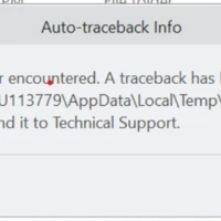
Hi, can you help me with this problem? It's the first time I see it Thank you
Hi, I have a cylindrical part, known the materials My goal is find the shear force to cut this cylinder, it's possible to obtain it with simulate Thank you for your help Have a good time!
Hi, can I install Creo in ARM-based windows? If yes can someone share links for installation help. I am planning to install it in Parallel desktop in Macbook Pro M1 release. @MartinHanak could you help on this?
Downloaded for school and entered correct licensing information from the Unistudent-standard.pdf file. Opening up Creo Simulate it is saying it is unable to get required simulate license. Before this - we uninstalled and reinstalled everything multiple times because opening any Creo program it would say there was no license despite inputting on during the setup install. Any help would be greatly appreciated.
I'm afraid that the answer is no...but can I use Datum Planes as the references for my Broken View?
Hello I was wondering if anyone had any additional insight to display the dimensions of a .prt level inheritance feature in a table at an assembly level drawing (Currently using Creo 4.0). Background: I have a .prt file that contains an inheritance feature, from which vardim is used to change the length of a feature example: d3:iid_843 is modified using vardim. The .prt is placed in an assembly. I would like to be able to display the dimension d3:iid_843 in a drawing table of the assembly. There seems to be 2 options for this but would really like a third option if possible. Option 1 If the .prt is placed as model in the assembly level drawing and activated, I can reflect the d3 dimension in the table using &d3:iid_843 • Adds an "active model" to the drawing (not ideal for WC revision control) Option 2 Create a relation in the .prt file, ex L1=d3:iid_89 and then place in the assembly drawing table using the correct session ID of the componen
Upon starting Creo 7 on my computer I receive a warning message list that shows license request failures. The license is on a coworkers computer and Creo 7 starts for him. Creo 5 still starts for me working off of the same license, but will not allow Creo 7 to start. Attached is the message I get.
Hi everyone, I'm trying to create an ejector pin for a casted part, and I'm using a copy geometry feature to reference the shape of the well in the component (in the image, the copied geometry is painted yellow, and the pin component is grey) The surfaces that I'm referencing from the casting are part of a solid model, but that's making this more difficult when I try to recreate that shape on the end of the pin. Because the copy geometry is from surfaces derived from solid geometry, I can't copy everything and once in order to make a quilt that I can then use to either solidify a cut or use as the end condition of an extrusion. I've tried using intent references and creating a seed and boundary quilt in the casting model, but nothing is really working. How can I take surfaces from my copy geometry and integrate them into the shaft of my ejector pin as solid geometry?
I'm having an issue with my datum filter not showing anything such as planes or coordinate systems and points. I have them checked and have show annotations but that gives me an error of "No annotations can be shown for the selected objects.". I'm using Creo 4. Any help would be appreciated.
Hi All, I am trying to fix the index in a table governed by Repeat Region. But I am not able to fix it as it displays error at the bottom bar : "Can not fix index due to symbol fam". Can anyone help me. I would appreciate your help.
Hello.I'd like to download the Student Edition of CREO Parametric 7.0 (free and with different file format not compatible with commercial version). How to do that ? Which is the correct URL on PTC site ? Is it different from Academic Edition ?Many thanks Pier
Hello, I'm modeling a set of rails for a part holding fixture that I'm designing. I have three different part sizes that I need to accommodate, but the shape of the part does not change. I modeled the rails using a top down methodology referencing a generic skeleton instance. I thought I would be clever by then making family instances for each of the needed sizes. Since the reference surfaces don't change, only the dimensions. I figured that in each assembly the rails would update on regeneration to match the skeleton instance. But this isn't the case, the references are still tied to the generic, and any attempt to re-reference brings up a warning that I have external references that I'm breaking. That must mean that the parts can only be referenced to a single instance of the skeleton at one time, which suggests that I need a family table for each rail as well. That brings me to my question, what's the point of family tables if I have to practically re
Hello, can you help me to understand the meaning of "Direction of Base Excitation"? Thank you
Some customers asked us about the possibility of DME components in EMX – the tooling application for Creo Parametric. For this development, we have selected DME Europe as a component partner. We have now already implemented the first batch of types in Expert Moldbase Extension, with more to follow. Find out more about which components are already implemented here.
Hi everyone,when I create a mirror assembly with File> Save As> Save mirror assembly and check the flag to keep the dependency because in case of modification of constraints or assembly features these do not update?Only the individual components within the assembly are updated. It's normal?
I always want material removal simulation to stop where tool must be changed. How to make this a default?
Hi I'm using the Creo ver 4.0 m100. I'd like to know size control option of Model tree feature structure. please look at the below image (in Red box) please help me
I am trying to install the newest verison on Creo and cannot get it to work. First it wouldn't recognize the license. I think I fixed that, but when I try to run the software now I get this message. Any ideas on how to fix this?
Already have an account? Login
Enter your E-mail address. We'll send you an e-mail with instructions to reset your password.