Recently active
I am using Creo Parametric Release 8.0 and Datecode8.0.0.0I am making Custom hardware for the AFX library based on the vendors we use (Automation Direct vs 8020.net) - When I add my new hardware (New Connector Equipment) the first one adds correctly with the right Part number in the model tree (151099.prt), but anything after the first defaults to the base part name (t-nut_ad.prt) which is controlled by the tab file similar to the bolt_kit parts in the 8020 libraryEdited to add - This is the command string when trying to add the subsequent parts which is supposed to be additional 151099:151099 regeneration completed successfully.Part '151099' not changed since last regen.T-NUT_AD has been saved.Select axis as component reference: PLACEMENT_AXISSelect face as component reference: PROFILE_SURFACET-NUT_AD regeneration completed successfully.Part 'T-NUT_AD' not changed since last regen.C
Working with Creo 10 Rev: 10020:I created a new drawing and with "show annotations" I can show dimensions of my part features in all the views.But when I click on a shown dimension the tolerances tab is grey and I'm not able to show tolerances of the activated dimension in the drawing. I can add/see/edit this tolerance of dimensions in the part itself.Even More strange is, that in old drawings this works without a flaw!Can you tell me what I do wrong?
I have used Mathcad Prime 10.0.1.0 for one month and I would like to purchase the full software for one year. I am a student at University of Wisconsin and would like to purchase the student version. When I select to buy and provide my info, I get a dialog that says to watch my email for a link. That email never comes. Can you help me purchase the student version? Thank you - Dave
I have converted the template from 15 to 10 and now i am trying to use the reference file but the there is error as attached. But i could not find any error in the reference file. In reference file i am reading the data from excel. But no errors here.
Could you please assist me with integrating the attached function in Mathcad? It represents the probability density function (pdf) of the Gamma distribution. I know that the integral should evaluate to 1, but I am unsure how to perform the integration in Mathcad without specifying the values for alpha and beta. When I assign specific values to these parameters, the integral correctly evaluates to 1, but I would like to achieve this result symbolically.Your guidance on how to proceed would be greatly appreciated.
Hi, I would like to change PTC mathcad langage without re-install in order to have the right translation of french error notification.Do you know how to do that ? Thanks PTCmathcad 9.0
Hi,I created a subassembly that I wanted to export for the top-level assembly. Since the subassembly file size is huge, I can't use it directly in my top-level assembly. Could you please suggest if there is a way to export the assembly (envelope) parametrically so that I can use it in the top-level assembly?
Using the piping module you can use the Pipe Solid to create pipe parts.These pipe parts have no material. You can add material in the line stock but like many options in creo, this doesn't do anything (doesn't even change the weight/length in the same menu lol)My question is simple: How can I add material to the piping parts (without doing it manually for every single piece of pipe ofcourse)I can think of two options:Option 1: Through the line stock material option.but since that option doesn't do anything...Option 2: Through relations. In the linestock I can fill in stock number which shows up as a parameter in the part. I want to add a relation to the template of the pipe part (still have to find out which template it uses and how to modify it) which basically says: IF stocknumber == A, then material =A. IF stocknumber == B, then material =B etc. Can anyone help me out?
Creo 9.0.6.0Dear PTC team, I want to figure out how to customize Ribbon via Creo TOOLKIT. To do it I launch an example from Creo 9.0.6.0\Common Files\otk\otk_cpp\x86e_win64\obj called otk_install.zip. When the auxiliary application is active I see that the Ribbon has changed and have a new group (20250228_screenshot_1.png). To save Customized Ribbon I follow the next steps from the User's guide:1. Go to File -> Options -> Options2. In "Creo Parametric Options" window go to Ribbon press Export->Save Auxiliary Application user interface. Then I check resulting toolkitribbonui.rbn (attached) or creo_parametric_customization.ui (depends on Export option) and can read nothing cause the encoding is incorrect.It seems strange cause initial file otk_install_test.rbn is readable. What 's interesting is that if I try to import Ribbon from the creo_parametric_customization.ui file, it works seamlessly, which makes me think
Hi I have a rotating mechanism that travels a total of 60degrees. An inner part rotates with an outer part for the first 40 degrees, and then stops rotation and moves in a linear vertical direction for the last 20 degrees. The vertical motion is driven by a ramp on the inside surface of the outer part. See screenshots. I'm using creo 3. Can anyone help show a good way to set up this connection? I have the 2 parts moving correctly independently but I can't figure out how to make the parts move together correctly.
Salve Ho scaricato da sito della PTC Creo Elements Direct Modeling Express 8.0 (English).All'accesso mi da il seguente errore: Come posso fare per risolverlo?In attesa di una risposta vi ringrazio anticipatamente. Ciao
I try to convert mathcad 15 Taylor serie to PTC mathcad 9.0.It seems that mathcad 15 could treat Taylor series with several variables but not PTC mathcad 9.0.After PTC conversions, PTCmathacd 9.0 give the following error : more than one independant variableCould you help me to solve this problem ? Thanks
Hello! I would like to ask the community about the mesh validation. There is a tool for it in CREO Simulate that is useless for a big simulation models (100000+ elements) it is impossible to turn the model while the mesh is displayed. So is there any feature or tool that will help to hide the valid elements and show only bad elements on the screen. Thank you for the response!
Hello, I've been trying to find those files all around Windchill and my local PC but didn't succeed in that. Where does creo simulate save mesh files?
I have a default set of units that are included in my document template. They are there because I use them regularly. Having a bit of fun, I have attached a sheet with these and about 50 more. Who doesn't compare area to Rhode Island or volume to a cord of firewood? Feel free to add more.Bob
Hi,I am getting the error pop up when trying to save file in a Specific folder. "Error Writing file; check disk space or write permission." * This Is the Error I am Getting Error only on 3 Specific folders only. (I have all access permission. to the drive). Other folder in the same drive are working fine. 1. I have created a new folder tried to save some files it works fine but when i copy 11GB of all drawing file and paste it in the same new folder i am getting the same error.2. i am able to copy and paste using file explorer it works.3. only with CREO i am getting error writing file. Recently our organization changed local Server to Cloud Server from then i am getting the error. Kindly help me in Resolving this issue. Regards.SAM
We have some models that are Creo 10 and some are Creo 9. We are working with another company that can open Creo 9 models and not Creo 10. Is there a way i can save Creo 10 models to Creo 9 without losing features and Metadata?
Following up on thr thread https://community.ptc.com/t5/Mathcad/LeastSquaresFit-usage-for-Foster-Model-parameters/td-p/100070 Why does genfit blow up when provided with the actual Foster Model thermal fitting function and guess values used within that model when fitting to @VD_12953418 digitized plot data? I would have guessed that the genfit result would have been close to the plot of the model or to the example of digitized data.
Hello I ran the setup.exe file and i get this error message: V:\pim\x86e_win64|installmgr.dll is either not designed to run or Windows or it contains an error. Try installing the program again using the original installation media or contact your system administrator or the software vendor for support. Error status 0xc0000020 Does the setup has to be installed in the desktop as opposed to a mount drive? I am not sure if is the dll file itself or my Windows 11 (i do have window universal c runtime as MS visual c++ Redistributable). I read somewhere here to download the dll file for creo 2.0 but i havent seen one for creo 10. I am still on the fence if it could be something else thanks
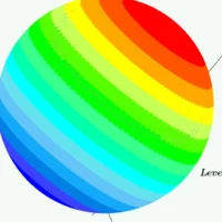
Green shows circle of half.
Hi,I have to create three Datum Axes with name D, E, F, based on a custom Coordinate System ("CS_DEF"), which is rotated relative to the original (XYZ) coordinate system.My problem is that, if I create a Datum Axis based on the axis of the coordinate system, Creo puts the axis name on the opposite side of the direction of the coordinate system's axes.How can I move the name of the axis to the opposite side?thank you
Hello All,Just wondering how people go about creating simplified models of sub assemblies. The specific thing I am working on is an assembly with several different bearings. While I want to keep the bearings in the assembly and it is nice they look like bearings when sectioned etc I would like to to simplify them. By simplify I mean ideally turn them into a single part. The bearings currently are as downloaded from the bearing supplier and each one has a dozen different parts. For this project I want to keep everything in a single folder and having lots of bearing parts is making it more difficult to see the other parts. Also I have to email assemblies and it would be better if the bearing was then just one part, instead of several. I could remodel the, but this seems time consuming and unnecessary. I also could Shrinkwrap them, but this creates external surfaces only. Any recommendations would be appreciated.Thank you.
Hi All, My PTC supplier adviced me to reinstall Creo and update to a newer version to get rid of another issue.I used to work with 8.0.4.0 and now I'm on 8.0.12.0, the previous issue is gone but now I got an even worse issue back!In this new version I can't get mechanism constraints to work. No matter what I do I'm not able to finish the constraint since it keeps saying "Connection definition is incomplete".Normally when I make a simple "Pin connection" I select an axis or round surface to align, then two surfaces to determine the rranslation and when this is done a new definition set appears to define the rotation. Now it will never show this rotation definition and I can't finish the constraint either. Any idea what this could be? Can it be a setting somewhere or is it a bug in the software? Thanks in advance!
I want to hide a part of an assembly in one of the detail view of the drawing but the parent view must have that part to be shown.Can anyone help me on this.
An option to automatically purge features in a model with no internal or external reference. This is for cleaning the model after finish the model.
Already have an account? Login
Enter your E-mail address. We'll send you an e-mail with instructions to reset your password.